Escrito por Tom Welch
The Miami Dade Water and Sewer Department Implements Dewatering Upgrades, Including Sludge Storage Hoppers, at South and Central District Wastewater Treatment Plants
The Miami Dade Water and Sewer Department (WASD) owns and operates three wastewater treatment plants, including:
- North District Wastewater Treatment Plant (NDWWTP)
- Central District Wastewater Treatment Plant (CDWWTP)
- South District Wastewater Treatment Plant (SDWWTP)
WASD is faced with the dual challenges of providing increased treatment capacity for growth, while also preparing for more stringent discharge requirements at each of these facilities. The principal components of the system associated with CDWWTP were constructed in the 1950s and 1960s. Although the system has been growing and expanding for the last 50 years, the last major expansion and upgrades at the CDWWTP were completed in the 1980s. The plant is located on Virginia Key and was originally constructed in 1956, making it the oldest existing wastewater treatment facility owned and operated by the WASD. The original permitted capacity of 47 MGD has increased to 143 MGD (AADF). But, due to the deterioration of the facility and the temporary nature of the structures housing the dewatering equipment, the CDWWTP requires the replacement of the thickening and dewatering facilities in the new design build project.
The current CDWWTP dewatering facility is housed in a 2-story structure located near anaerobic digester Cluster Four. Feed solids range from 1 to 4% solids and are dewatered to approximately 23% solids. After processing, the dewatered sludge is discharged onto trucks for transport into the onsite biosolids storage building. Due to lack of storage, if trucks aren’t available, the centrifuges are forced to shut down.
The SDWWTP serves the southern and southwest portions of the county and is located in the southeastern part of Miami Dade County. It is currently permitted to treat (AADF) of 112.5 mgd. The sludge that is generated in the wastewater treatment process is removed from the liquid stream, then dewatered using centrifuges. The dewatered biosolids are discharged onto a covered screw conveyor. From the screw conveyor, the biosolids are discharged into a truck and transported to the drying beds for further dewatering via evaporation before landfill disposal or composting. The SDWWTP has the same problem as CDWWTP, if trucks aren’t available, the centrifuges are forced to shut down.
-
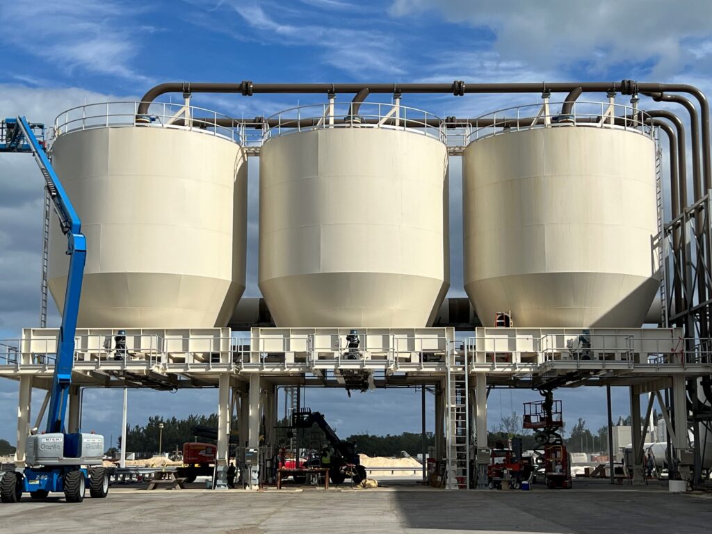
- Miami Dade Central WWTP
-
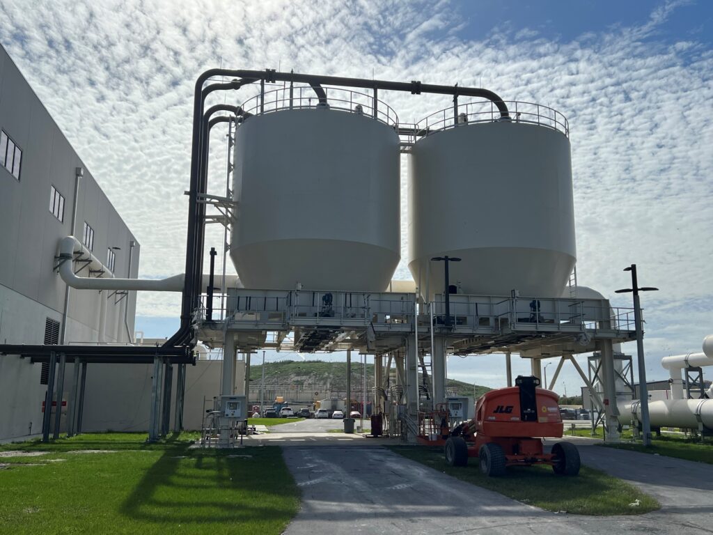
- Miami Dade South WWTP
At the CDWWTP and SDWWTP facilities, the new design build project adds three dewatered cake storage silos at CDWWTTP and two dewatered cake storage silos at SDWWTP. Each has a capacity of 500 cubic yards, which provides two days of cake storage at each facility. During design, the original concept was to use a cake silo that had a live bottom comprised of four screw conveyors, which distributes sludge to two discharge points. Each discharge point would have had two knife gate valves. Discharge rates from each silo is sized at 3300 cubic feet per hour, which would allow loading a 30 cubic yard truck in about 15 minutes. Adding the truck loading silos improves the efficiency of the material handling and removes the current bottleneck at the solids discharge end of the plants.
Schwing Bioset, based on their multiple years of experience with providing truck loading silos to improve efficiencies in utilities, worked closely with the Design Build Team to provide an alternative design of a sliding frame silo compared to the original live bottom bins:
- Sliding frame silos utilize an ellipse shaped frame that slides on the floor of the silo, actuated by a small hydraulic power unit. Sliding frames are used throughout North America and the world as a lower cost alternative to live bottom systems for both large and small biosolids storage systems. Sliding frame technology includes the following beneficial features:
- Round silo design eliminates the need for external stiffeners to maintain shape, compared to live bottom designs. This reduces steel fabrication requirements and improves housekeeping as there are no ledges to accumulate water, solids, or provide bird nesting sites.
- Reduces maintenance requirements, as the key sliding frame maintenance points are the stuffing box on the silo and the oil filters on the hydraulic power units, compared to the large spur gear/chain drive gear boxes commonly associated with live bottom systems.
- The use of silos simplifies the integration of load cells when specified.
- Increases useable capacity as noted in greater detail below, illustrated in the following 3D models. The dashed blue lines indicate the bin/hopper shape, and the shaded gray areas indicate how the biosolids will fill within the system.
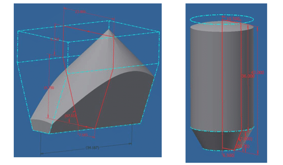
- As noted above, the alternate sliding frame silo can increase usable capacity. The Live Bottom design shown on the left would only fill to 322 cubic yards at 45° AOR with the center inlet. When using a different inlet location, capacity was further reduced to 297 cubic yards. Whereas the proposed sliding frame silo, shown on the right, would fill level to near 500 cubic yards.
- The original live bottom design did not have space between the bins for stiffeners or field installation. Alternate sliding frame silo design eliminates stiffeners on the sidewall and leaves clearance for field installation.
- Likewise, clearance between columns and bins are required for effective use of load cells. Alternate sliding frames silo provides sufficient clearance.
- Discharge slide gates are offered to hydraulically actuate, with an auto close feature upon activation or loss of power of E-stop activation, in lieu of the originally designed electrically actuated gates. Gates would be powered by the sliding frame silo hydraulic unit.
- Sliding Frame system affords the use of four outlets over the two originally included, with the live bottom to allow greater flexibility in load-out operations.
With construction being sequenced between two plant locations, final completion and commissioning is scheduled to take place over 2024 and will carry the plant through the 2035 design basis.
Contáctenos today to learn how Schwing Bioset can help your operation, or Visite nuestro sitio web to read more about our products and solutions.
Descargue nuestros folletos e informes de aplicaciones Subscribe to Start Receiving Schwing Bioset eNews